
Do not simply replicate the milled part.
Design the blank properly.
A milled-part geometry adopted 1:1 often exploits the possibilities of A-MIM only in part. Even so, an existing design is a sensible starting point. Whether it is suitable as is, or becomes more economical with modifications, has to be checked on the specific part.
Three questions that should be kept apart
1
Is the application fundamentally suitable?
Do size, shape, material and quantity fit the process family? The existing design is sufficient for this.
2
Does the part improve with modifications?
For example consolidating functions, equalizing wall thicknesses, saving material. This is an option, not a prerequisite.
3
What does manufacturing need?
Position in the build space, sintering support, shrinkage compensation, machining allowances. This process design is part of manufacturing.
The guidance on this page helps with question 2 – anyone who prefers to have the part checked unchanged first can do so. To the part check
What works well as a blank
A-MIM can produce shapes that would be either impossible or disproportionately expensive to mill:
Internal channels
Freely shaped internal cavities
Fluid routing, cooling, relief – without drilling from outside
Undercuts
Geometry without a demolding direction
No mold required; whether an undercut can be built depends on the printing process (e.g. support requirements, depowdering)
Function integration
Several functions in one part
Bracket + channel + port in one as-sintered blank
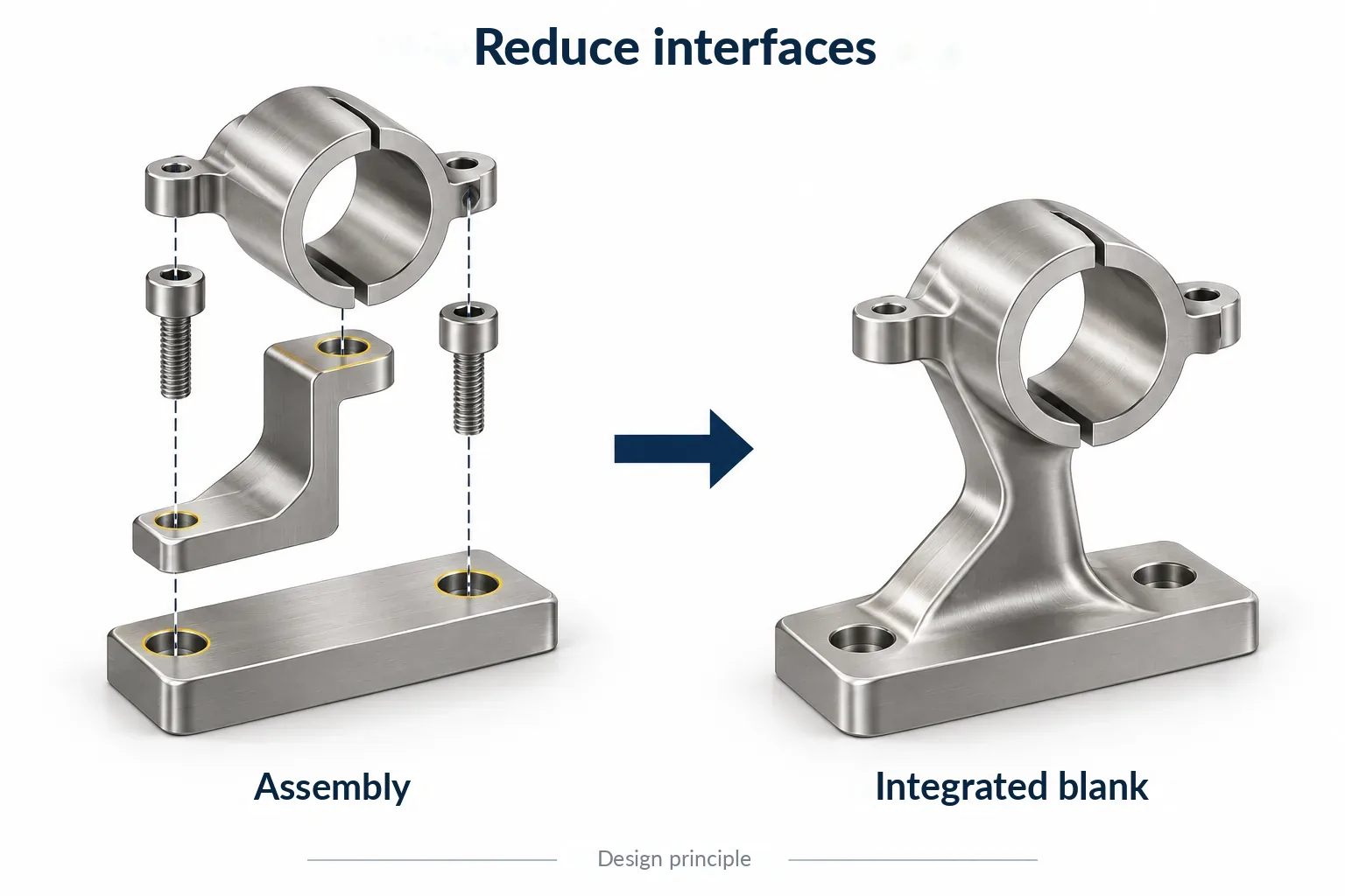
Assembly reduction
3 parts become 1
Joints, assembly and the associated inspections can be eliminated – the leak test of the finished part remains
How a part can be improved for A-MIM
1
Think blank first
Do not only ask “How do I mill this?” but also “What can the blank already deliver?” Which surfaces are post-processed follows from that.
2
Integrate functions
Place channels, pockets, ribs and ports directly in the blank – do not plan them as later machining steps.
3
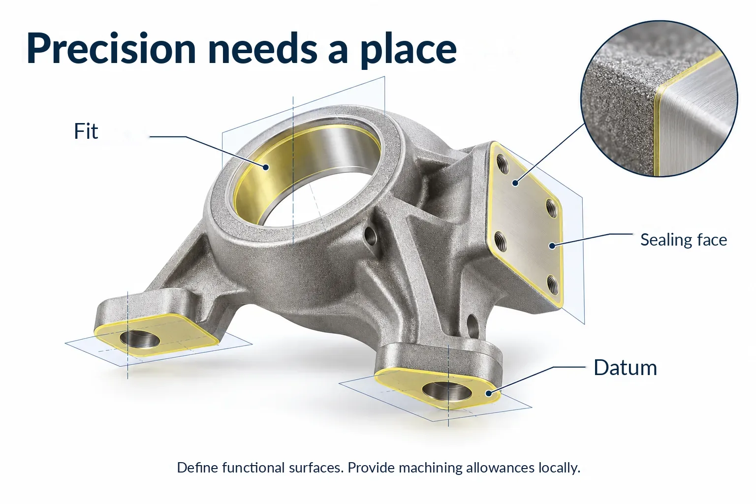
Define critical surfaces deliberately
Which surfaces need a tight tolerance or a better finish, and which do not? The answer determines the extent of machining.
4
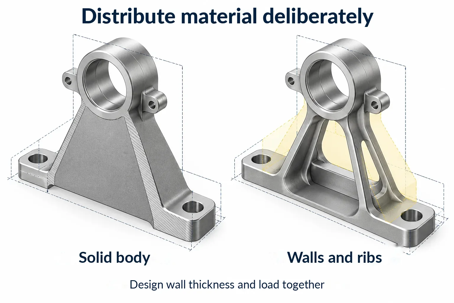
Avoid mass where it is not needed
Massive areas next to thin walls shrink unevenly and can warp. Keep wall thicknesses as uniform as possible, with no unnecessary solid material.
Typical design guidelines
Do not think only in terms of a milled part
Design the geometry for the sintering process
A milled-part shape adopted 1:1 can be suitable, but often does not exploit the advantages
Plan for local rework
Plan from the start what will be machined
Provide stock allowance on machined surfaces – but only there
Uniform wall thicknesses
No abrupt change from thick to thin
Unevenly distributed mass shrinks unevenly
Consider sintering behavior
How does the part sit in the furnace?
Large unsupported surfaces, overhangs – account for them early
Sintering behavior is not just a process parameter – the design influences it as well.
Understanding sintering →