
A-MIM Technology
Process chain, process variants and materials in detail.
Process chain
1
Printing (green part)
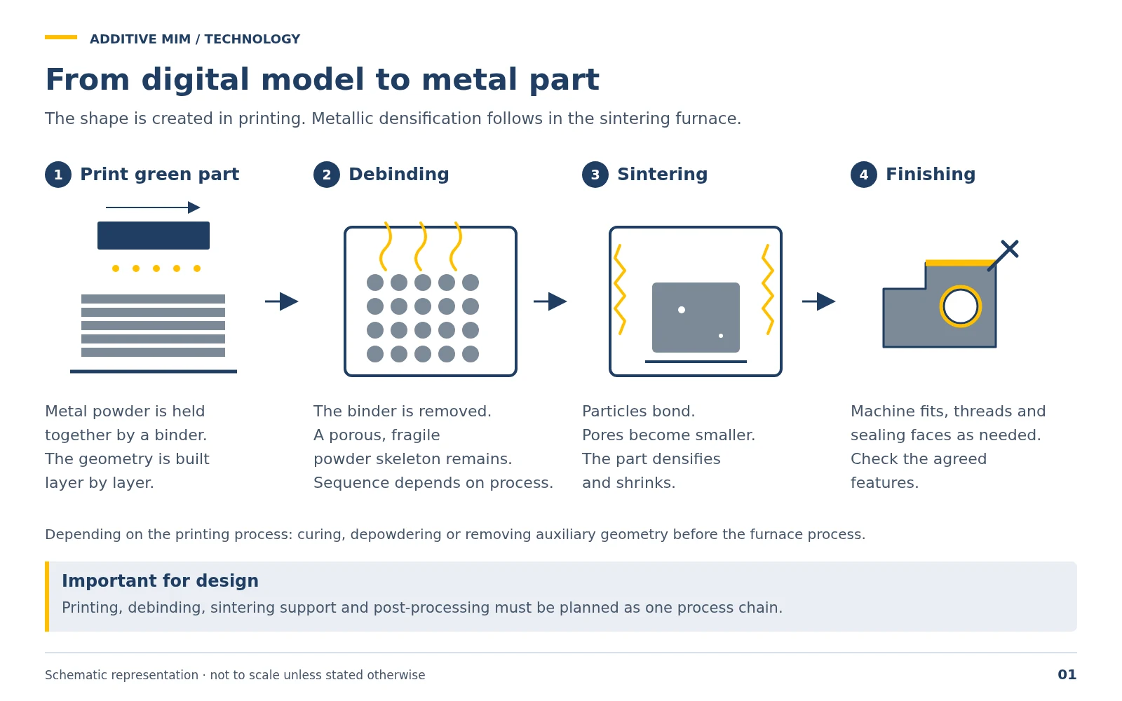
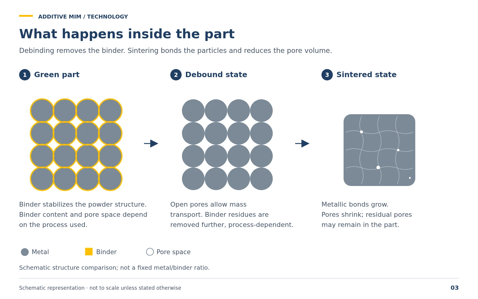
Metal powder is built up layer by layer with a binder to form the green part – the not yet sintered, mechanically fragile part. The binder content depends on the printing process.
2
Debinding
The binder is removed, depending on the process thermally, with solvent or catalytically. What remains is a porous part that holds together only loosely.
3
Sintering
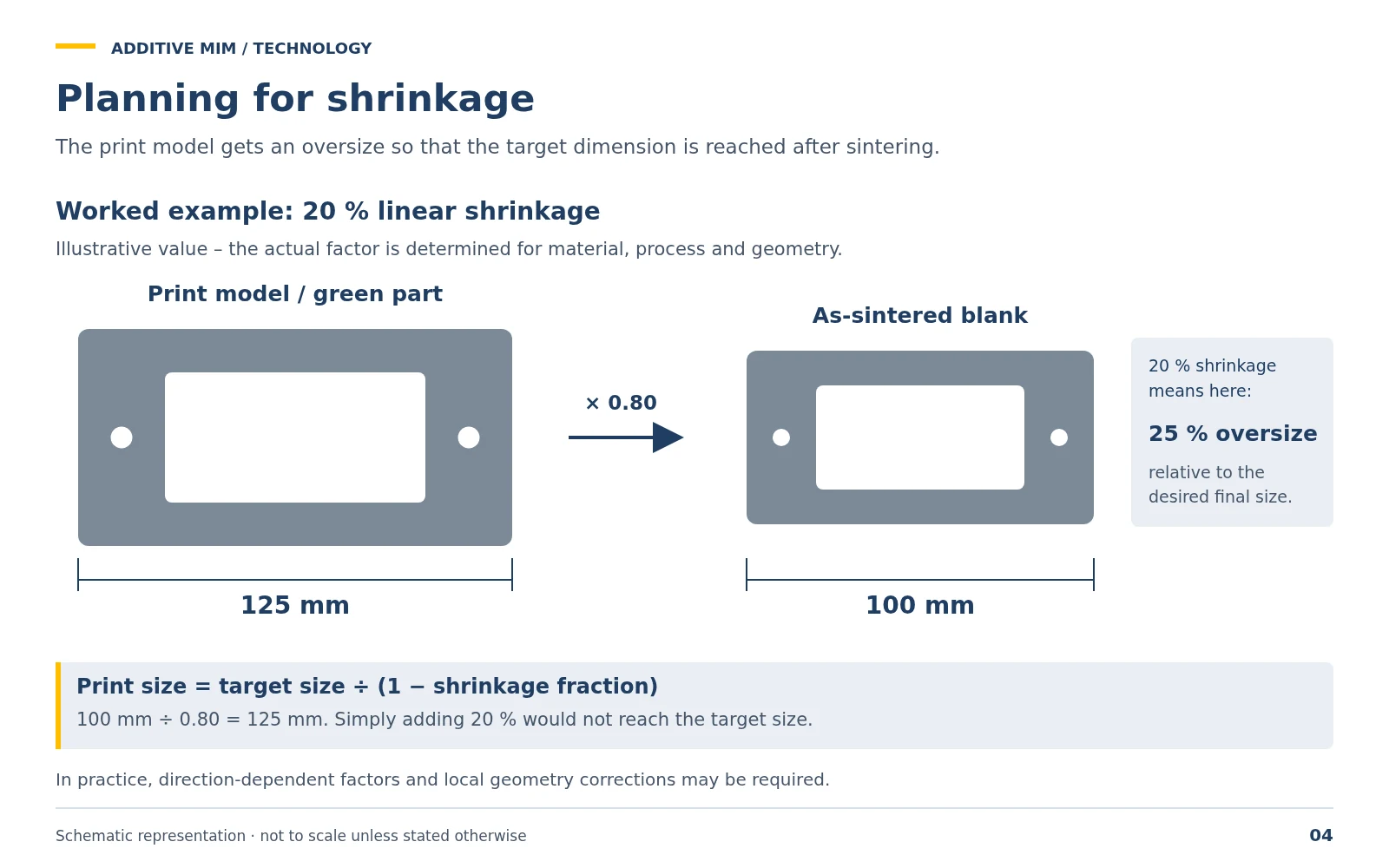
At a material-dependent temperature below the melting point, the metal particles bond, the pores become smaller, and the part densifies and shrinks – as a guideline by about 15–20 % linear, not the same in all spatial directions.
4
Finishing
Machine fits, threads and sealing surfaces where required, inspect agreed features.
Process variants
| Process | Principle | Typical characteristics |
|---|---|---|
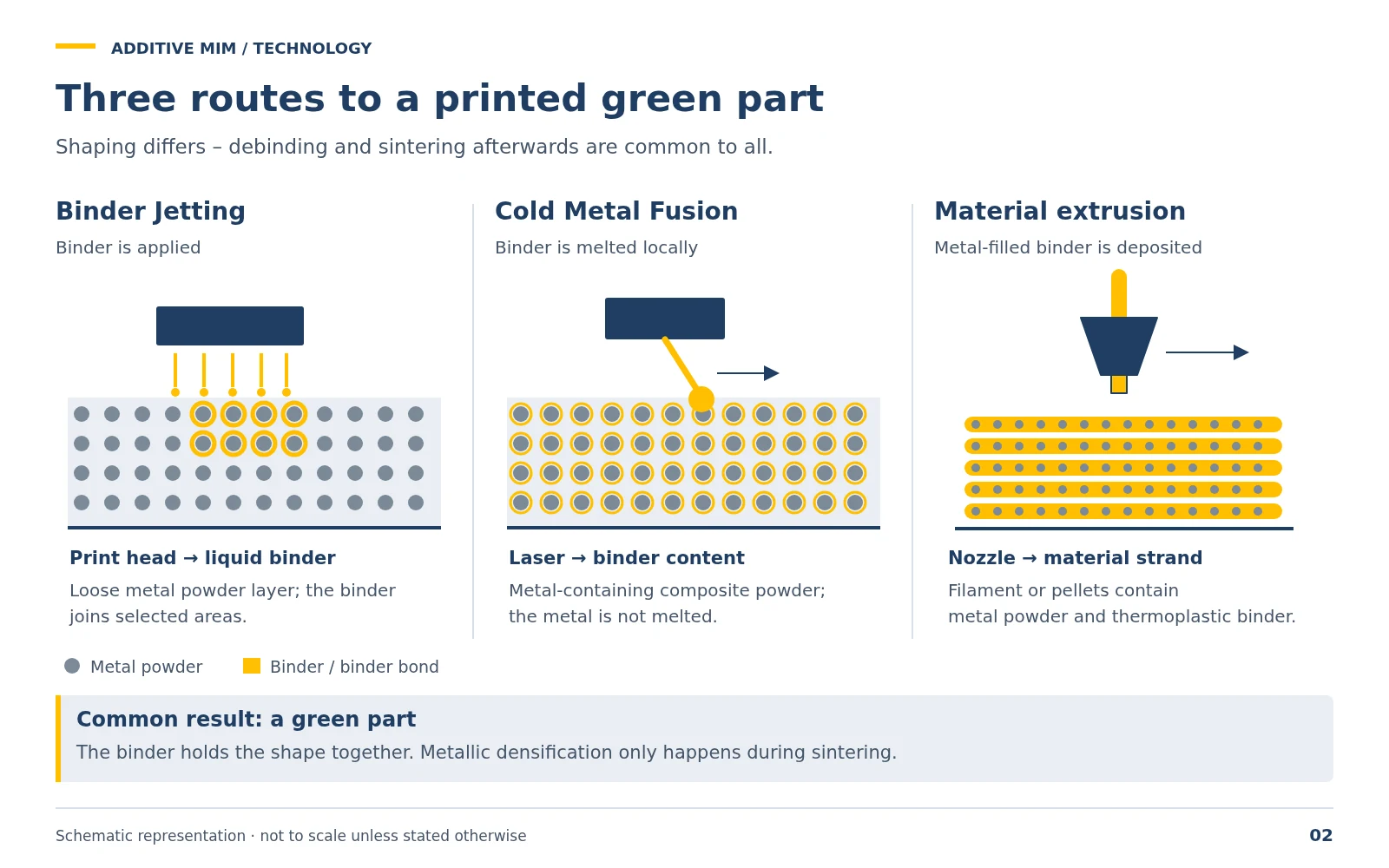
| Binder Jetting | A print head applies liquid binder layer by layer onto a metal powder bed. | Parts are supported in the powder bed, and many parts fit into one build volume. Example HP Metal Jet: layer thickness 35–140 µm according to the manufacturer. |
| Cold Metal Fusion | A laser locally melts the polymer fraction of a composite powder; the metal is not melted. | The green part is comparatively stable to handle thanks to the polymer binder. Characteristic values depend on the manufacturer. |
| Material extrusion (Metal FFF) | A filament or granulate of metal powder and binder is heated and deposited track by track. | Depending on the geometry, overhangs need support structures. Characteristic values depend on the manufacturer. |
Layer thickness is not the same as the achievable detail resolution or part accuracy. These additionally depend on powder, binder, in-plane print resolution, debinding, sintering and post-processing.
Materials – examples from the process family
The table shows materials that can in principle be processed with sinter-based printing processes. Which of them are actually available for a given process and provider varies – the overview is not a product range.
| Material | Type | Typical application |
|---|---|---|
| 316L | Austenitic stainless steel | Medical, food, chemical |
| 17-4PH | Precipitation-hardening stainless steel | Aerospace, mechanical engineering |
| Tool steels | H13, M2, etc. | Molds, tools, wear parts |
| Nickel-based alloys | Inconel 625, 718 | High temperature, corrosion |
| Copper | Pure copper, CuCr | Heat exchangers, electronics |
| Titanium | Ti6Al4V | Medical, lightweight construction |
Achievable properties
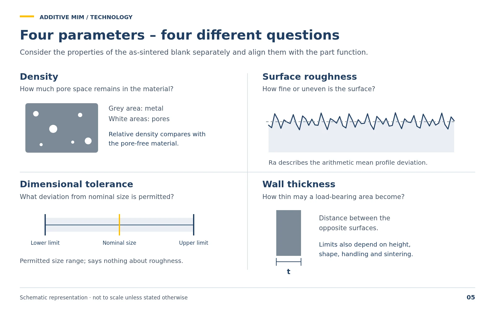
The characteristic values depend on material, printing process, process control and part. There are no universally valid figures for all materials; binding values are given in the data sheet of the respective material and process.
Density
How much pore volume remains
Example binder jetting with stainless steel 316L / 17-4PH (HP Metal Jet): above 96 % after sintering according to the manufacturer. Post-densification (HIP) can increase it further.
Surface roughness
Depends on powder, layer and orientation
In the as-sintered state rougher than a machined surface. Functional surfaces are machined, polished or blasted where required.
Dimensional tolerance
Coarser as sintered than as machined
Depends on part size, geometry, material, support and shrinkage compensation. Tight tolerances are achieved through post-processing.
Wall thickness
Limited downward by the process
Minimum values depend on process, height, shape, handling of the green part and orientation during sintering.