
Geometry decides.
With wire-based DED, the perfect final contour is not printed. What is created is usually a near-net-shape blank.
The central question is not:
“Can this CAD geometry be built exactly?”
Rather:
“Which volumes must be built up additively — and which details are created later by milling, drilling, grinding, or other post-processing?”
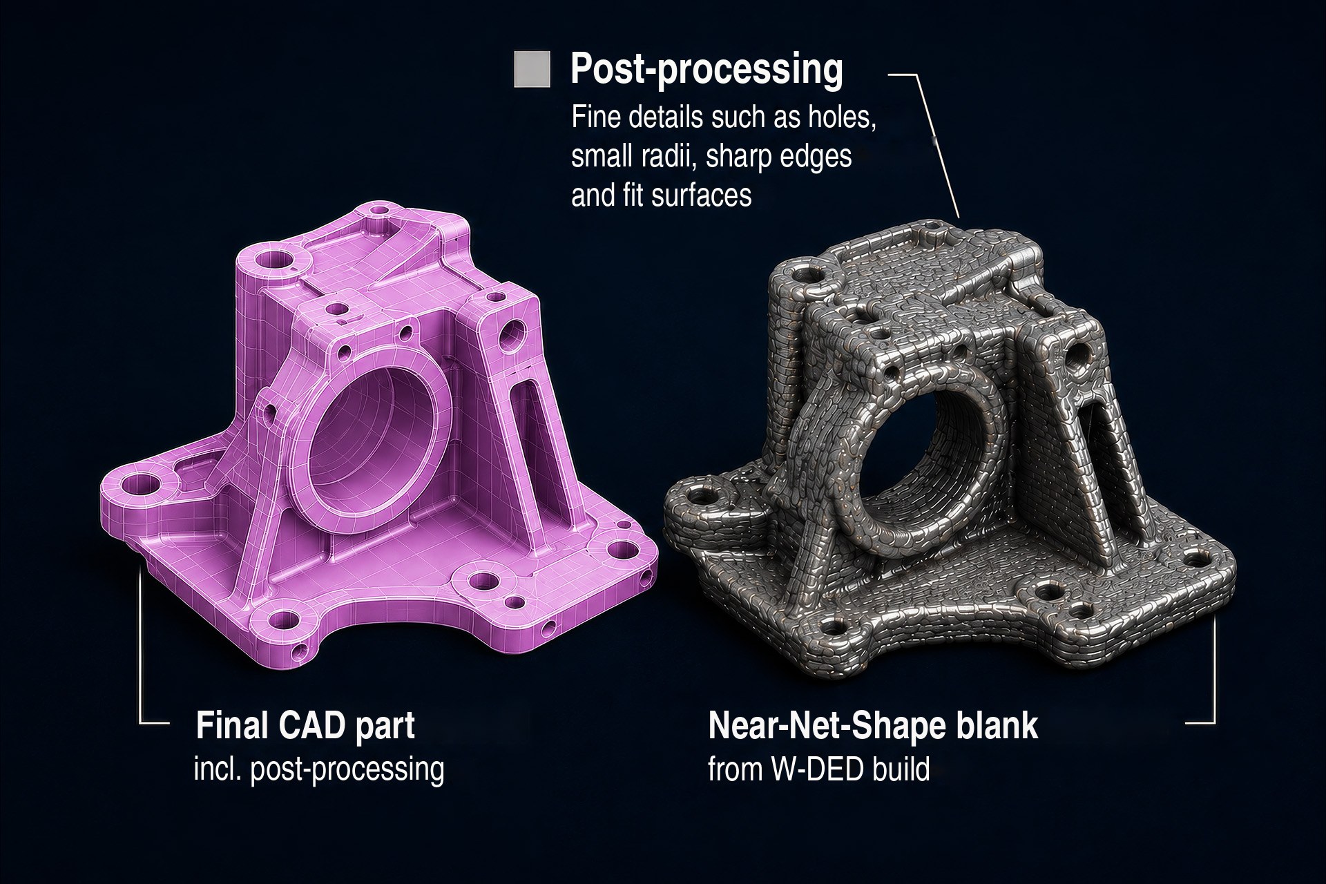
Not every detail belongs in the build.
Wire-based DED works with weld beads, melt pool, and machining allowance. As a result, there is a sensible minimum size for geometric features.
Small details are not “finished” additively but are machined out of the built-up blank later.
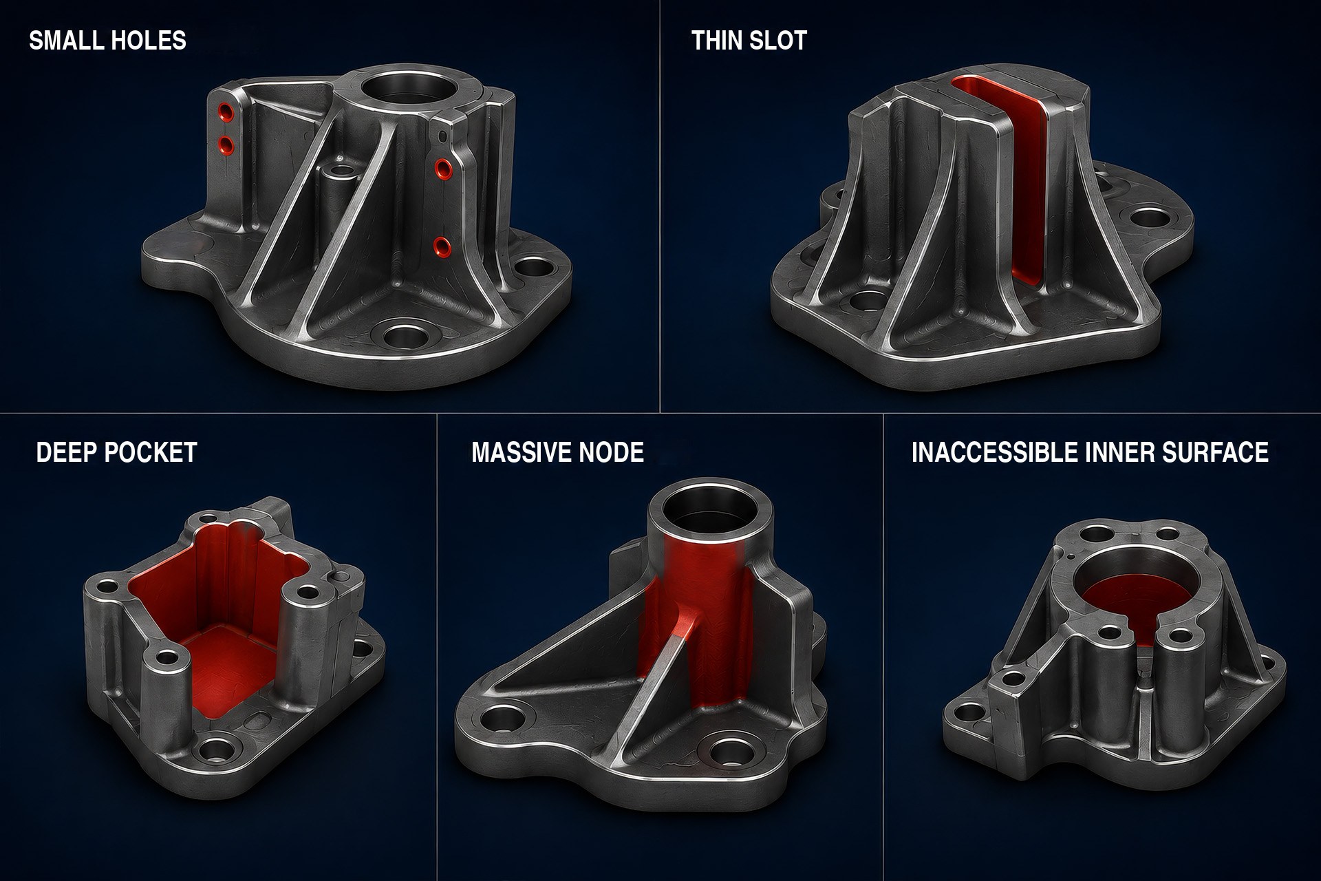
Critical features
- Small bores
- Narrow grooves
- Thin webs
- Sharp inside edges
- Small radii
- Fine ribs
- Threads
- Mating surfaces
- Sealing surfaces
- Filigree contours
Suitable features
- Solid ribs
- Local material pads
- Repair zones
- Reinforcement areas
- Coarse functional volumes
- Large transition radii
- Accessible exterior surfaces
- Machining allowances
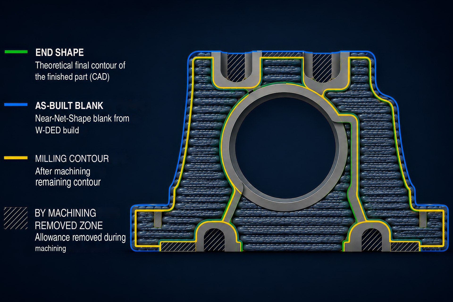
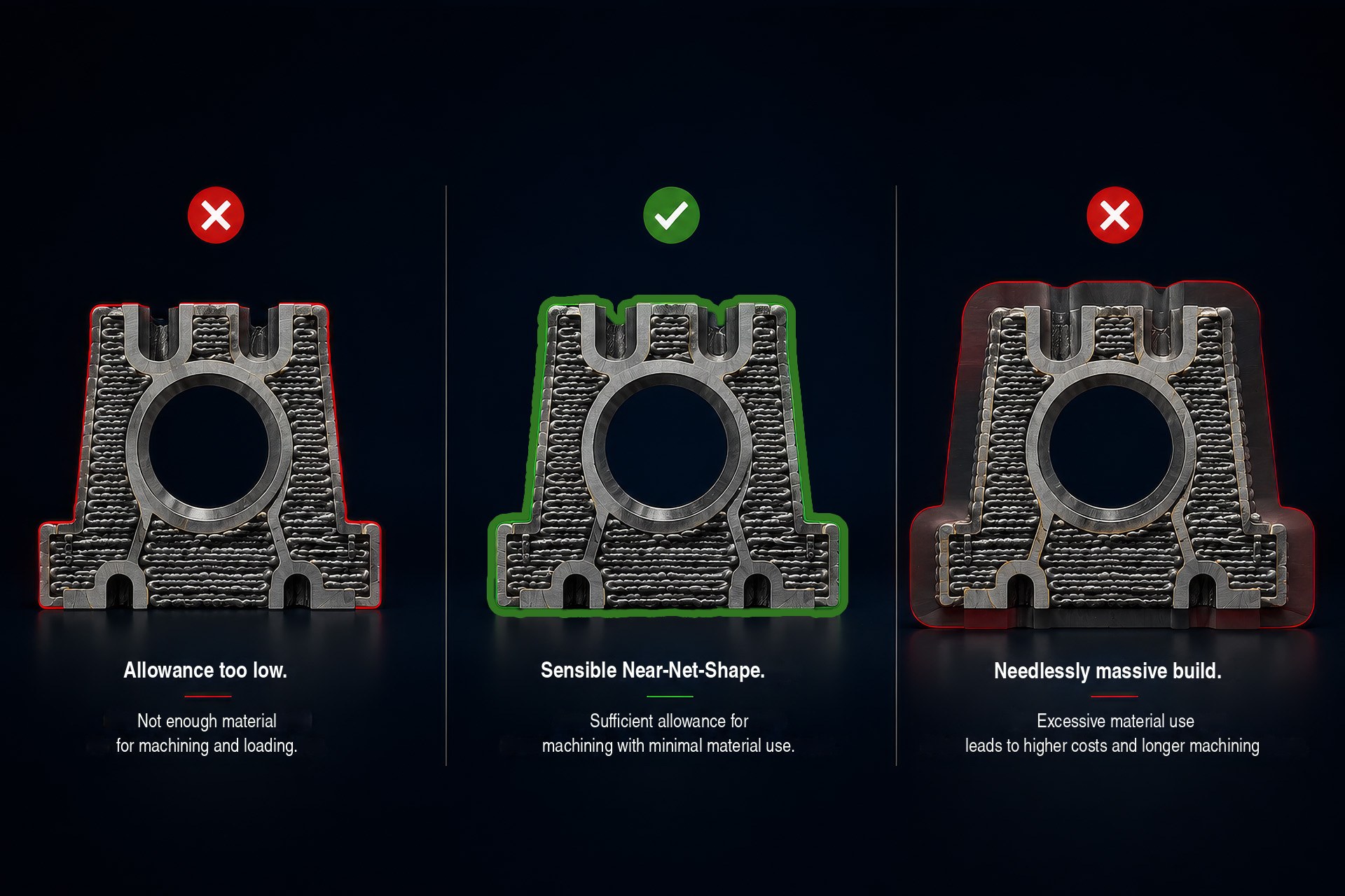
The blank has to be designed correctly.
The built-up body is an intermediate state. It must contain enough material for the final contour to be machined out reliably. At the same time, it must not become unnecessarily massive, because additional material deposition adds time, heat, and rework.
Good geometry here means:
as much build-up as necessary, as little build-up as possible.
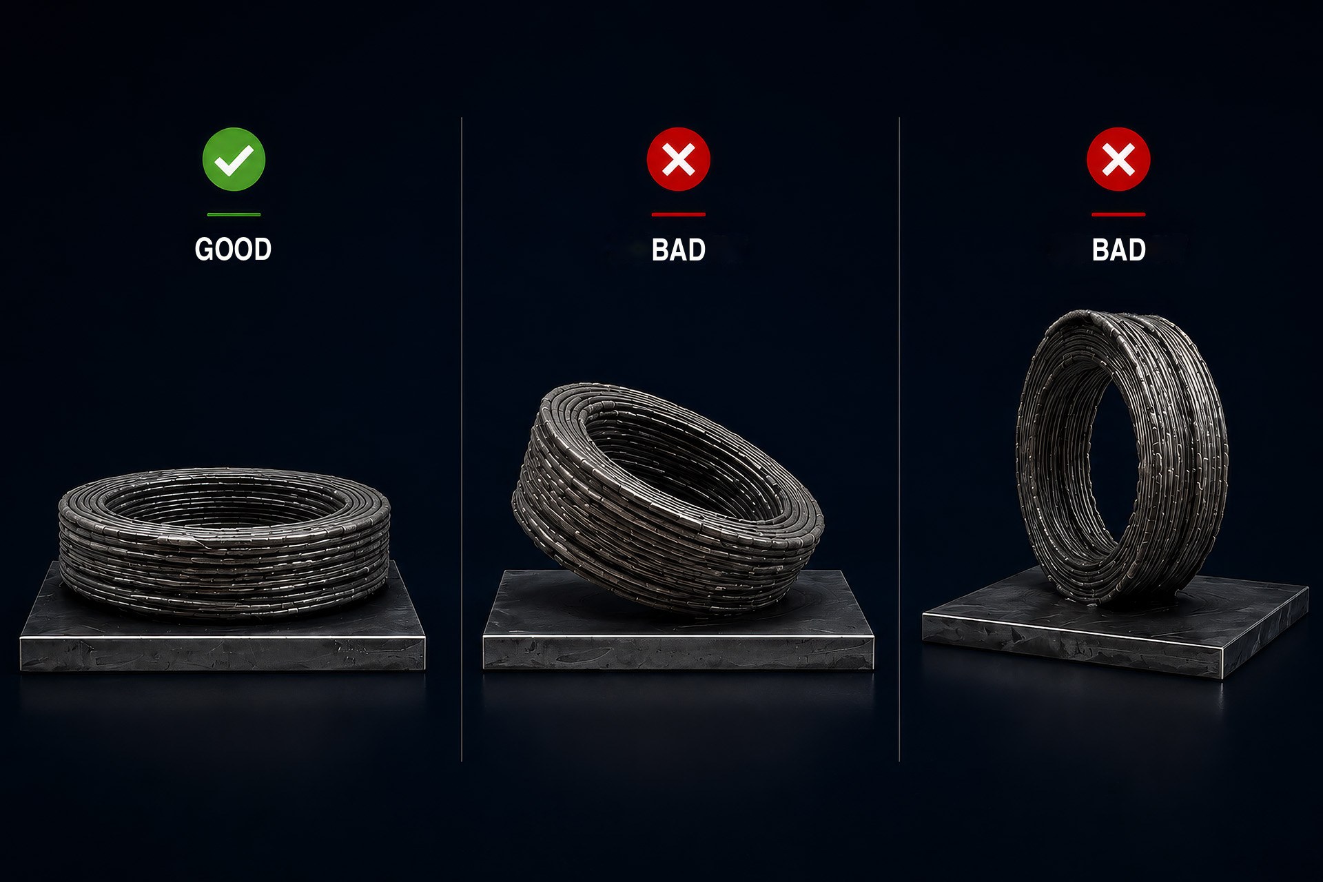
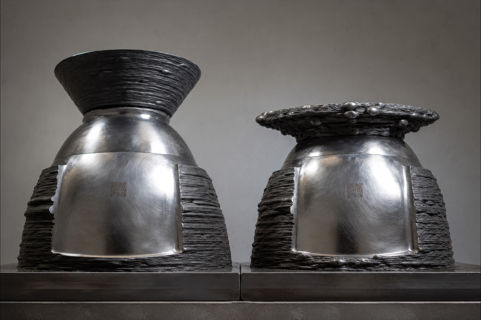
The same geometry can be easy or difficult.
Depending on orientation, the bead path, heat input, overhang, collision risk, and later machinability change.
The build direction determines whether a blank can be built stably, accessibly, and economically.
Liquid metal needs support.
Wire-based material deposition produces locally molten metal. Unfavourable overhangs can make weld beads unstable, let material sag, or lead to excessive machining allowance.
With near-net shape, the goal is therefore not perfect free form but a stable blank that can be post-processed.
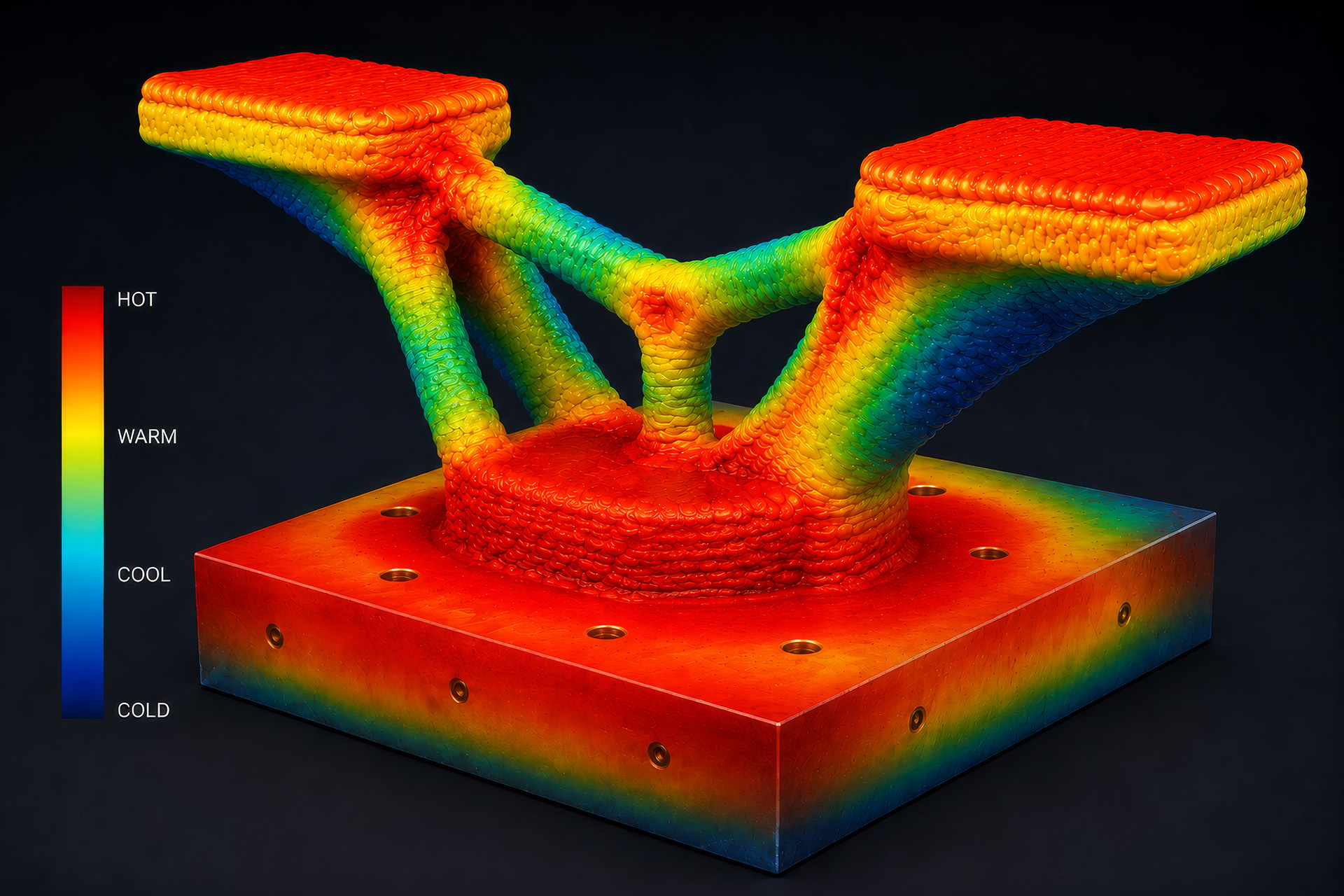
Mass stores heat.
Solid regions, thick nodes, and rapid cross-section changes can trap heat. This affects solidification, stress, distortion, and the quality of the subsequent layers.
A near-net-shape blank must therefore not only fit geometrically. It must also make sense thermally.
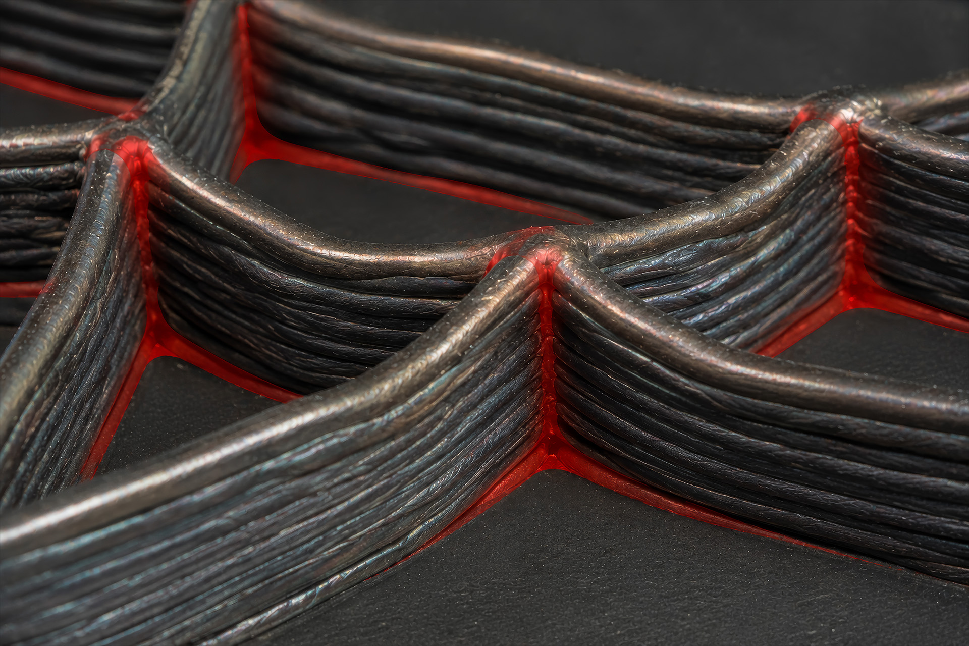
What cannot be reached stays raw.
The process head needs room for material deposition. Later, the milling machine needs room for the final contour.
Critical are therefore not only build zones but also regions that cannot be machined cleanly after the build.
Critical
- Deep pockets
- Narrow interior regions
- Concealed undercuts
- Inaccessible mating surfaces
- Inner contours without tool access
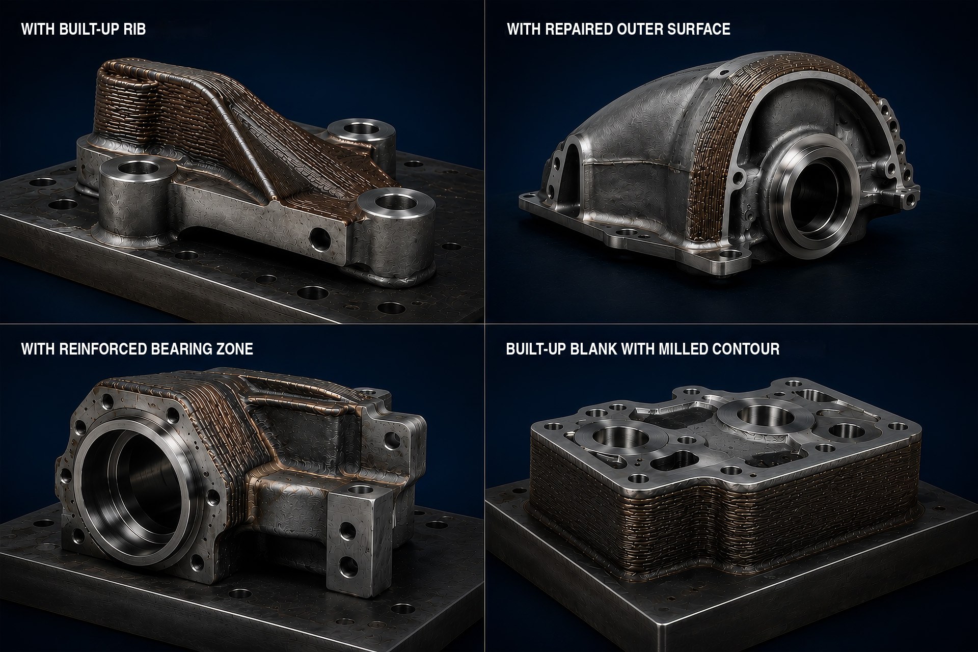
Good geometries separate raw form and final form.
Suitable are parts where the additive build creates coarse functional volumes and the precise features are machined afterward.
Suitable
- Large ribs
- Local reinforcements
- Repair surfaces
- Solid functional areas
- Accessible exterior contours
- Clear machining allowances
- Simple post-processing directions
It becomes critical when the final contour is to be built directly.
Problematic are geometries that expect small details, tight tolerances, or hard-to-reach interior regions directly from the build process.
Critical
- Filigree webs
- Small inside radii
- Precise bores without rework
- Sharp edges
- Deep internal channels
- Concealed functional surfaces
- Solid heat nodes
- Narrow gaps
- Visible surfaces without machining allowance
Geometry is the first filter.
Wire-based DED becomes interesting when the blank can be built sensibly and the final contour can be reliably post-processed.
The decisive questions are:
- Which volumes must be built up?
- Which details are better produced by post-processing?
- Is the build thermally stable?
- Are the process head and tool accessible?
- Does an economical near-net-shape blank result?