
W-DED: Where Are the Manufacturing Limits?
Laser wire, WAAM and SAAM compared directly – from fine structures to massive metal blanks.
The geometric possibilities of wire-based additive manufacturing are largely determined by the weld bead geometry, the layer height and the heat input. Laser wire DED, WAAM and SAAM differ considerably in this respect. Choosing a suitable process depends not only on part size, but also on the required wall spacing, surfaces, tolerances and post-processing options.
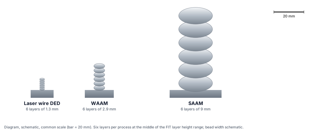
Three Processes – Different Manufacturing Limits
| Parameter | Laser wire DED | WAAM | SAAM |
|---|---|---|---|
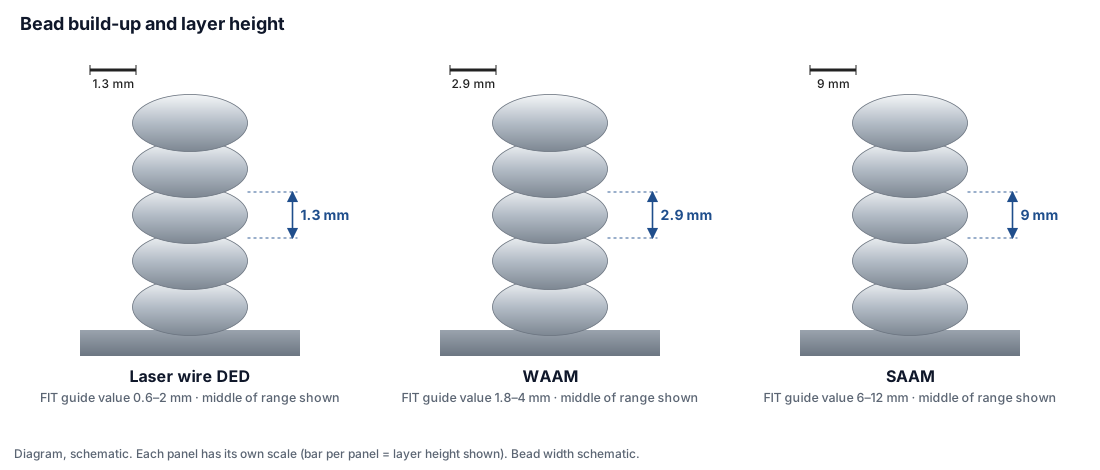
| Layer height | 0.6–2 mm | 1.8–4 mm | 6–12 mm |
| Minimum spacing between walls | 2 mm | 4 mm | 12 mm |
| Peak-to-valley profile height (≈ 0.3 × layer height) | 0.18–0.60 mm | 0.54–1.20 mm | 1.80–3.60 mm |
| Minimum machining allowance per side | 0.6 mm | 2 mm | 4 mm |
Layer height, minimum spacing and machining allowance are FIT process guide values. The peak-to-valley profile height is a calculated indicative value: peak-to-valley profile height ≈ 0.3 × layer height. The factor 0.3 is a provisional FIT design assumption, not a generally established literature value. The minimum spacings apply to adjacent walls in the as-built state; the exact measurement definition is being confirmed internally at FIT.
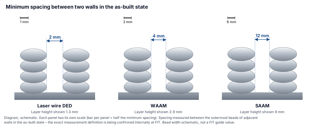
How Close Together Can Two Walls Be?
The minimum spacing does not result from the wire diameter alone. It depends on how wide the melt pool and the weld bead become, and on whether the deposition head can still work between two walls. Key influencing factors:
- Melt pool width and weld bead geometry
- Heat input and thermal interaction between adjacent walls
- Accessibility for the deposition head
- Height and depth of the resulting structure
- Material and process parameters
A short, open gap must be assessed differently from a deep, narrow channel: the deeper the gap, the harder accessibility and heat dissipation become, and the more the two walls influence each other. The minimum spacing is a distance between two walls – it says nothing about the smallest producible wall thickness.
Design solution: Narrow gaps are better produced by subsequent milling from solid material, by design openings that let the head in, or by a different build sequence in which the walls do not grow at the same time.
Why W-DED Surfaces Are Wavy
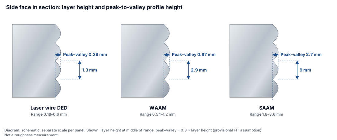
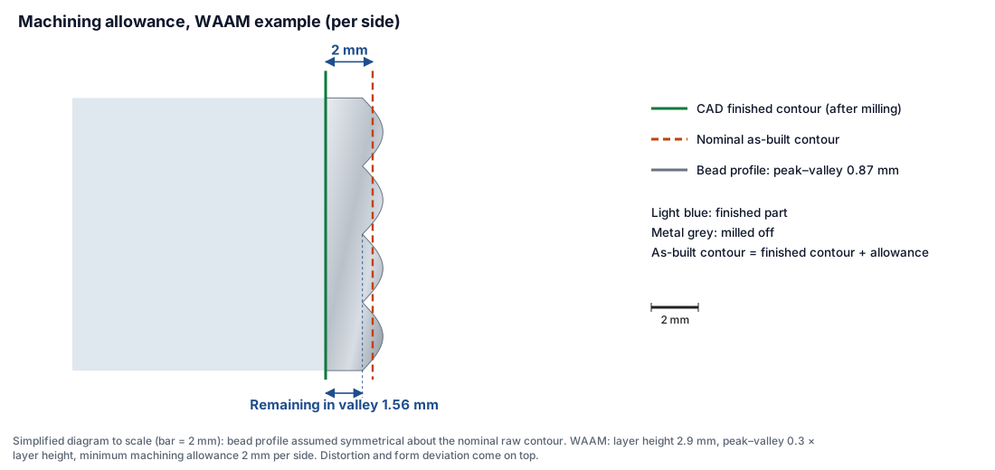
The side faces are formed by stacked weld beads. Each layer bulges outwards; a constriction forms between two layers. This creates characteristic bead peaks and bead valleys.
With the factor 0.3, the peak-to-valley profile height follows from the layer height:
| Process | Layer height | × 0.3 = peak-to-valley profile height | Example at range midpoint |
|---|---|---|---|
| Laser wire DED | 0.6–2 mm | 0.18–0.60 mm | 1.3 mm → 0.39 mm |
| WAAM | 1.8–4 mm | 0.54–1.20 mm | 2.9 mm → 0.87 mm |
| SAAM | 6–12 mm | 1.80–3.60 mm | 9 mm → 2.7 mm |
How Much Material Must Be Allowed for CNC Machining?
Functional surfaces are milled from the additive blank. The required allowance depends on the deepest point of the profile relative to the desired finished contour. Form deviations and distortion must also be taken into account. The allowance cannot be determined from the peak-to-valley profile height alone. FIT minimum values per side:
| Process | Minimum machining allowance per side |
|---|---|
| Laser wire DED | 0.6 mm |
| WAAM | 2 mm |
| SAAM | 4 mm |
The FIT minimum allowances given are for guidance and are checked for the specific part. They are not a guarantee that every part geometry can be fully machined.
Which Geometries Are Critical?
Thin walls
The smallest wall depends on weld bead width, heat input and part height. Tall, thin walls dissipate heat poorly and can deflect. We do not state a blanket minimum wall thickness here.
Solution: Build the wall thicker additively and mill it to size, or stiffen tall walls with ribs.
Bores
Small, dimensionally accurate bores cannot be produced additively to the required accuracy.
Solution: Build bores solid and then drill, ream or mill them; only pre-form large openings additively.
Internal channels
Accessibility, the bead structure on the channel wall and – for SAAM – the removability of powder and slag are decisive.
Solution: Build channels as an open groove and close them with a cover, or drill them afterwards.
Overhangs
Whether an overhang succeeds depends on build direction, support from the bead underneath and process control. We do not state a blanket limit angle without a reliable definition.
Solution: Orient the part so that overhangs are avoided, build in multiple axes, or produce the part in sections.
Thermal distortion
Distortion depends on part size, cross-section, heat input and build strategy.
Solution: Symmetrical build-up, interpass cooling, a clamping fixture and an allowance that also covers the distortion.
Functional surfaces
Sealing surfaces, fits and bearing seats achieve neither the form nor the surface finish in the as-built state.
Solution: CNC-machine these surfaces as a rule and plan the allowance for it from the start.
Which W-DED Process Suits My Part?
Laser wire DED
Smaller structures, local material deposition and finer geometric resolution.
- Layer height 0.6–2 mm
- Wall spacing from 2 mm
- Machining allowance from 0.6 mm per side
WAAM
Medium to large structural parts with flexible geometry and a comparatively high deposition rate.
- Layer height 1.8–4 mm
- Wall spacing from 4 mm
- Machining allowance from 2 mm per side
SAAM
Large, massive metal blanks with an emphasis on high material deposition and subsequent machining.
- Layer height 6–12 mm
- Wall spacing from 12 mm
- Machining allowance from 4 mm per side
The selection is a technical guide. Whether a process is economically worthwhile for a part depends on material, quantity and machining effort and is assessed case by case.
Not Every Geometry Has to Be Built Additively
The example shows a part with a sealing surface, a bore and a 3 mm wide slot. The slot is below the WAAM minimum spacing of 4 mm and is therefore not built additively:
- Initial geometry: the finished part with functional surfaces, bore and narrow slot.
- Additive raw geometry: a simple envelope without slot and bore, with 2 mm machining allowance per side.
- CNC-machined finished part: sealing surface milled, bore drilled, slot milled.
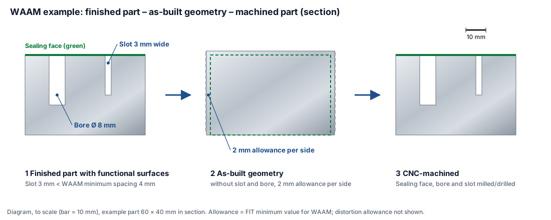
The right combination of additive build-up and conventional machining determines the technical and economic quality of the solution. How this looks on real parts is shown in hybrid manufacturing.
Which Limits Apply to Your Part?
Manufacturability depends on geometry, material, part size and functional requirements. FIT assesses which W-DED process is suitable and which design adaptations or post-processing steps make sense.
Check part for manufacturability →Where the Values Come From
- Layer height, minimum spacing between walls, minimum machining allowance per side: FIT process guide values of FIT AG (as of 31.10.2026).
- Peak-to-valley profile height: calculated as 0.3 × layer height; the factor is a provisional FIT design assumption, not a literature value.
- Diagrams: drawn from these values; the midpoint of the layer height range is shown in each case. The bead width is schematic (2.5 × layer height) and not a FIT guide value.
- General design notes on internal channels, overhangs and post-processing of wire-based processes (for explanation, not as FIT equipment values): MX3D, How do you design parts for WAAM?